
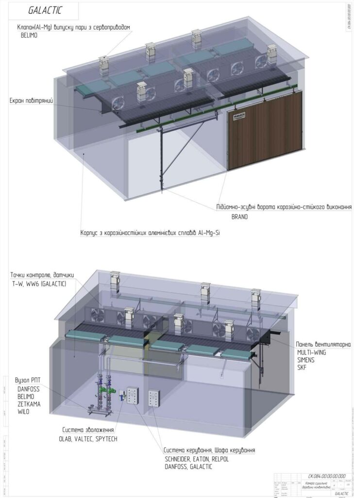
Chamber for drying lumberensures drying of lumber according to the 1st quality category with an average final moisture content of 7-10% of lumber or blanks; with a deviation of the moisture content of individual boards (blanks) from the average moisture content of the lumber stack of no more than ± 1.0%; moisture drop across the thickness of lumber (blanks) of no more than 1.0%.
The design and equipment of the chamber provides high performance indicators - low energy consumption of the drying process, high reliability of the supplied equipment, simplicity and convenience of personnel work, warranty and post-warranty service.
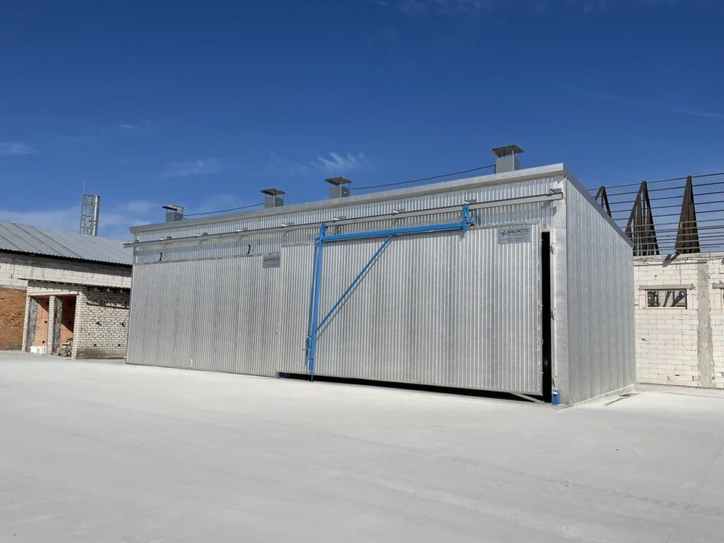
Camera body is a modular frame structure. The frame is made of 5-8 mm thick profiles made of aluminum alloy AD-31 (6063). The inner lining is made of profiled aluminum-magnesium sheet with a thickness of 1.0 mm, the insulation is basalt slabs 55-80 kg/m2. The thickness of the insulation layer in the walls is 150 mm. The ceiling is made of sandwich panels with polyurethane filler 120 mm thick. A 0.8 mm thick profiled aluminum sheet is used as the outer cladding.
Fan panel - a complete technological unit for inducing the circulation of the drying agent (cross-blowing of the lumber) inside the chamber. Structurally, it consists of a fan frame that is part of the frame and circulating axial fans built into it.
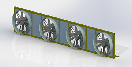
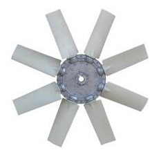
The frame equipment includes reversible impellers of F900 mm fans from Multi-Wing (Denmark) with an efficiency of up to 75% to ensure air supply through the stack in order to achieve a circulation speed of 2-2.5 m/s in the stack.
 High-quality electric motors manufactured by the concern are used to drive the fans SIEMENS with a high efficiency class with special high-temperature bearings SKF (Sweden).
The impeller of ideal geometric shape with perfect balancing in combination with a specially designed electric motor allows this unit to be operated in a timber drying chamber (temperature up to 80°C, humidity up to 100%) for up to 5 years (30 thousand hours) without routine maintenance (replacement of bearings, lubrication, etc.)
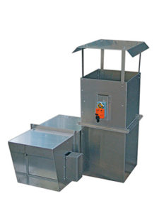
Steam outlet valves are made of corrosion-resistant aluminum-magnesium sheet with a thickness of 2 mm. In the manufacture of the valve, fasteners made of stainless steel are used. Uniform rotational movement of the gate valve is ensured by a shaft made of stainless steel, which moves in bushings made of acid-resistant, anti-friction polymer material.
The rotary movement of the valve is provided by a servo drive from Belimo (Sweden).
Heating system - transfers heat energy from the boiler to the drying chamber, uniform heating of the drying agent (steam-air mixture) throughout the drying chamber to evaporate moisture from the surface of the lumber. Structurally, it consists of a set of heat exchangers, a coolant pipeline, a coolant distribution unit with a circulation pump and a three-way valve with an electric drive.
Heat exchangers are made on the basis of bimetallic pipe. The heating surface is made of rolled aluminum fins, the support tube is made of carbon steel. The design of the heat exchangers ensures efficient heat transfer and low aerodynamic drag.
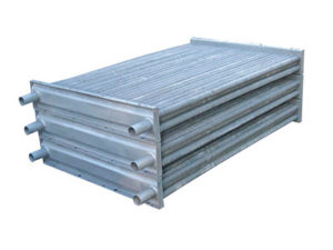
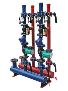
The heating pipeline is the main line for the flow of coolant from the DHW unit to the heat exchangers. The design of the pipeline ensures uniform distribution of the heat transfer fluid to the heat exchangers. The pipeline is equipped with devices for capturing and removing air that can impede the flow of coolant in case it appears in the pipeline.
The coolant control and supply unit (CCU ) consists of a three-way valve with an electric drive, a circulation pump, connecting pipelines and shut-off valves, and devices for monitoring the temperature and pressure of the coolant.
A properly selected circulation pump manufactured by WILO (Germany) ensures the movement of the required amount of coolant in the heating system. The Zetkama sediment filter (Poland) protects the pump from possible mechanical damage.
Shut-off valves, in the form of butterfly valves Zetkama (Poland), allow maintenance of the elements of the coolant supply control unit (CSU) (for example, filter cleaning) without draining the coolant from the system.
Danfoss (Denmark) three-way valve with Belimo (Sweden) servo drive regulates the amount of coolant that will flow into the heat exchangers on command from the control system in order to maintain the temperature in the chamber required by the drying mode.
Loading gate with opening mechanism
The gate design in the form of a one-piece, lift-and-slide panel provides the highest thermal insulation and airtightness. The door frame is made of a special aluminum profile and provides structural rigidity of the door. The inner and outer cladding is made of profiled aluminum sheet. A 100 mm thick insulation is placed between the panels. The perimeter of the door panel is equipped with a seal made of a special heat-resistant rubber compound.
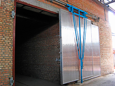 The perfect tightness of the unloading gate is achieved by using a profile made of a heat and vapor resistant rubber compound as a sealing material, high precision manufacturing of the gate panel and a system of adjustable clamps around the gate perimeter.
To open the gate (one-piece panel), the Opening Mechanism is used to lift the gate panel and move it along the Guide along the chambers. A powerful BRANO gearbox (Czech Republic) is used as a traction device of the opening mechanism.
.
Automatic control system MDR - 3456 is used to monitor and control the wood drying process in automatic mode.
Structurally, the system consists of:
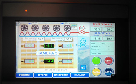
The system is completely autonomous. You can monitor and control the drying process via the Internet using any PC or smartphone.
The power cabinet is designed to control the actuators of the drying chamber (circulation fan motors, steam exhaust valve drives, three-way valve drive and humidification system valve).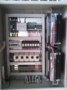
Products of the world's leading manufacturers Schneider, Eaton (Moller), Relpol, Socomec are used as components of the power cabinet.
The use of specialized circulating fan motor protection circuit breakers ensures 100% protection and timely disconnection of the motor from the mains in the event of abnormal or emergency operating conditions (absence of one phase, skew, voltage deviation from the norm).
The package includes high-temperature silicone cables for connecting the drying chamber fans.
| Technical characteristics | KS 30/5 |
KS 40/5 |
KS 50/5 |
KS 40/7 |
KS 50/7 |
KS 65/7 |
KS 50/8 |
KS 70/8 |
KS 85/8 |
KS 60/10 |
KS 80/10 |
KS 100/10 |
KS 80/13 |
KS 105/13 |
KS 130/13 |
|---|---|---|---|---|---|---|---|---|---|---|---|---|---|---|---|
| Internal dimensions of timber drying chambers: | |||||||||||||||
| width, mm | 5 000 | 5 000 | 5 000 | 6 500 | 6 500 | 6 500 | 8 400 | 8 400 | 8 400 | 9 800 | 9 800 | 9 800 | 12 800 | 12 800 | 12 800 |
| depth, mm | 6 100 | 7 400 | 8 600 | 6 100 | 7 400 | 8 600 | 6 100 | 7 400 | 8 600 | 6 100 | 7 400 | 8 600 | 6 100 | 7 400 | 8 600 |
| height, mm | 5 100 | 5 100 | 5 200 | 5 100 | 5 100 | 5 100 | 5 100 | 5 100 | 5 100 | 5 100 | 5 100 | 5 100 | 5 100 | 5 100 | 5 100 |
| Space for loading: | |||||||||||||||
| width, mm | 5 000 | 5 000 | 5 000 | 5 000 | 6 000 | 6 000 | 8 400 | 8 400 | 8 400 | 9 800 | 9 800 | 9 800 | 9 800 | 9 800 | 9 800 |
| depth, mm | 3 900 | 5 100 | 6 300 | 3 900 | 5 100 | 6 300 | 3 900 | 5100 | 6 300 | 3 900 | 5 100 | 6 300 | 3 900 | 5 100 | 6 300 |
| height, mm | 4 000 | 4 000 | 4 000 | 4 000 | 4 000 | 4 000 | 4 000 | 4 000 | 4 000 | 4 000 | 4 000 | 4 000 | 4 000 | 4 000 | 4 000 |
| Number of packages in height (1.2 x 1.2 m) |
3 | 3 | 3 | 3 | 3 | ||||||||||
| Number of packages in depth (1.2 x 1.2 m) |
3 | 4 | 5 | 3 | 4 | 5 | 3 | 4 | 5 | 3 | 4 | 5 | 3 | 4 | 5 |
| Volume of wood loaded into the chamber (conditional lumber)*, m3 | 30 | 40 | 50 | 40 | 53 | 65 | 53 | 68 | 86 | 59 | 79 | 99 | 80 | 105 | 130 |
| Type of fans | №8-6, 2,2kW | №8-6, 2,2kW | №9-7, 3,0kW | №8-6, 2,2kW | №9-7, 3,0kW | №9-7, 3,0kW | №8-6, 2,2kW | №9-7, 3,0kW | №9-7, 3,0kW | №9-7, 3,0kW | №9-7, 3,0kW | №9-7, 3,0kW | №8-6, 2,2kW | №9-7, 3,0kW | №9-7, 3,0kW |
| Number of fans, pcs. | 3 | 3 | 3 | 3 | 3 | 4 | 4 | 4 | 5 | 4 | 5 | 6 | 5 | 6 | 8 |
| Total capacity of of electrical equipment, kW |
7 | 7 | 9 | 7 | 9 | 12 | 9 | 12 | 15 | 12 | 15 | 18 | 15 | 20 | 27 |
| Heat output of the heating system, kW |
135 | 180 | 225 | 180 | 240 | 290 | 240 | 315 | 390 | 270 | 350 | 450 | 350 | 470 | 580 |
| Number of valves 380, pcs. | 2 | 4 | 4 | 4 | 4 | 4 | 4 | 4 | |||||||
| Number of valves 380, pcs. | 4 | 4 | 4 | 6 | 4 | 6 | 8 | ||||||||
| The installed capacity of the electrical equipment. | 7,1 | 7,1 | 9,7 | 7,1 | 9,7 | 12,7 | 12,7 | 12,7 | 16,5 | 13 | 16,5 | 19,5 | 16,5 | 20,2 | 26,2 |
| Technical characteristics | KS 750/3 РА | KS 1000/4 РА | KS 1250/5 РА | KS 1500/6 РА | KS 1750/7 РА | KS 2000/8 РА | KS 2250/9 РА | KS 2500/10 РА |
|---|---|---|---|---|---|---|---|---|
| Internal dimensions of timber drying chambers: | 5 rows of pallets, 4 rows of pallets in depth | |||||||
| width, mm | 4 200 | 5 400 | 6 600 | 7 800 | 9 000 | 10 200 | 11 500 | 12 800 |
| depth, mm | 7 400 | 7 400 | 7 400 | 7 400 | 7 400 | 7 400 | 7 400 | 7 400 |
| height, mm | 6 700 | 6 700 | 6 700 | 6 700 | 6 700 | 6 700 | 6 700 | 6 700 |
| Space for loading: | ||||||||
| width, mm | 4 200 | 5 400 | 6 600 | 7 800 | 9 000 | 10 200 | 11 500 | 12 800 |
| depth, mm | 5 000 | 5 000 | 5 000 | 5 000 | 5 000 | 5 000 | 5 000 | 5 000 |
| height, mm | 5 400 | 5 400 | 5 400 | 5 400 | 5 400 | 5 400 | 5 400 | 5 400 |
| Number of packages in height (1.2 x 1.2 m) | 4 | |||||||
| Number of packages in depth (1.2 x 1.2 m) | 4 | |||||||
| Number of packages in width (1.2 x 1.2 m) | 3 | 4 | 5 | 6 | 7 | 8 | 9 | 10 |
| Number of packages in depth (Euro pallet) | 5 | |||||||
| Number of packages in the chamber (1.2 x 1.2 m) | 48 | 64 | 80 | 96 | 112 | 128 | 144 | 160 |
| Volume of wood loaded into the chamber (palletized workpiece)*, m3 | 41 | 54 | 68 | 82 | 95 | 109 | 122 | 136 |
| Loading volume of euro pallets into the chamber, pcs. | 750 | 1000 | 1250 | 1500 | 1750 | 2000 | 2250 | 2500 |
| Type of fans | №9-6, 3,0kW | №9-6, 3,0kW | №9-6, 3,0kW | №9-6, 3,0kW | №9-6, 3,0kW | №9-6, 3,0kW | №9-6, 3,0kW | №9-6, 3,0kW |
| Number of fans, pcs. | 3 | 4 | 5 | 6 | 7 | 8 | 9 | 10 |
| Total power of electrical equipment, kW | 9,75 | 13,1 | 16,5 | 19,5 | 23,2 | 26,2 | 30 | 33 |
| Heat output of the heating system, kW | 230 | 320 | 390 | 460 | 530 | 600 | 670 | 740 |
| pump power, kW | 0,75 | 1,1 | 1,5 | 1,5 | 2,2 | 2,2 | 3,0 | 3,0 |
| Number of valves 480, pcs. | 4 | 4 | 4 | 4 | 6 | 6 | 8 | 8 |
| The installed capacity of the equipment | 9,75 | 13,1 | 16,5 | 19,5 | 23,2 | 26,2 | 30 | 33 |
Система SPAL - це модернізація сушарки, яка забезпечує інтенсивне сушіння укладеної на піддони деревини та інших швидкосохнучих матеріалів, скорочуючи час сушіння до 30%.
The system includes a heating system with a 20% increase in capacity, a 20% increase in air circulation system performance, and the addition of appropriate devices to the power cabinet. The chambers for drying euro-pallets are equipped with this option as standard. Optionally, turbofans can be installed for fast steam release.
Technological doors with an opening of 1400x600 mm are single-leaf. They provide quick access to the chamber for operational control of lumber and equipment. The doors are manufactured using the same technology as the door panel.
Theair humidification system is designed to increase the air humidity in the timber drying chamber during intermediate and final heat treatment. Air humidification is carried out by fine spraying of water through special nozzles made of stainless steel. Water is supplied to the chamber through an OLAB solenoid valve (Italy). The humidification system provides mechanical filtration of the water entering the nozzles to 1 micron, For effective operation of the humidification system, a water supply line with a pressure of 3-4 bar must be supplied.
EcoDry is an energy-saving dryer that reduces energy consumption by up to 50% when drying hardwoods and up to 20% when drying softwoods, while maintaining drying quality. It includes a frequency converter and optimized software to control the drying process.
Additional control point T+W - an additional measurement point for drying agent parameters. It allows for more accurate analysis of drying parameters.
12 wood moisture points (+6 additional) - 6 additional wood moisture measurement points. Refined analysis of wood moisture in the chamber.
The drying chamber body and components are assembled at the customer's production facility.
Before starting installation work, the Customer is required to:

